
ActiveG MapEngine™ User Guide
Version 3.0
Confidential and Proprietary – ActiveG © 2019 – All rights reserved.
Table of Contents
Getting StartedMapEngine on Another Monitor
MapEngine Menu Buttons
Selecting Map Features
Creating and Editing Work Orders from the Map
Saved Vicinities
Legend Window
Custom Work Order Layers
Summary Mode
Search
Go To
Building Mode
Measurement Tool
Proposing GIS Changes
Linear Work Orders
Overview
ActiveG MapEngine™ integrates IBM Maximo Enterprise Asset Management and ESRI ArcGIS in one map visualization application.
MapEngine provides a myriad of features for viewing and interacting with Maximo work orders, assets, locations, routes, and other GIS and Maximo information. It also provides the ability to generate and change one or many Maximo records via a map interface.
Getting Started
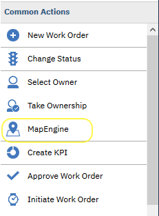
To get started with MapEngine, just log into Maximo and navigate to a MapEngine-enabled Maximo application. Typically this includes applications like Work Order Tracking, Locations, and Assets. From there, launch MapEngine by clicking the MapEngine icon. MapEngine will launch in a separate browser tab, but still be connected to Maximo on the backend and connected to the open UI in your other browser tab.
MapEngine uses your Maximo credentials from the open Maximo tab. So once you log into Maximo and launch MapEngine, there is no need to login from the map — you're ready to take advantage of all the map capabilities.
Map on another monitor
Because MapEngine runs in a browser tab separate from Maximo, you can view it in a separate monitor, (if you have two monitors, of course). Just click on the MapEngine browser tab and drag the tab into your second monitor. MapEngine will continue to be connected to your current Maximo session. At the close of your Maximo session, just close the MapEngine tab, if you're done viewing the map. If not, you can still view work order and asset data on the map, only without the Maximo update features.Selecting map features
Map selections are defined as any item on the map that are selected, highlighted on the map (usually in green or red), and listed in the Map Selected Features window. Selections can be performed on any active map layer. If more than one feature is in the same place, a list of features will be given in the place the user clicked to choose which he/she wants to select. There are a few different ways to create a selection:
Select by clicking on the map
 Using your cursor, click directly on a map feature to select it. Once selected, the feature will have a highlight, and will appear in the Map Selected Features list.
MapEngine prioritizes the selection of points, lines, and polygons in that order. This is useful in cases where several different feature types are in close proximity. If you want to select a line, click along a place in the line that is more distant from a point. Similarly, click a place on a polygon that is more distant from adjacent points and lines to only select that polygon.
Selectable Layers.
You can set a specific map layer to be selectable, meaning only that layer will be selectable by clicking or drawing. Before making a selection, choose a layer to select from. This is done in the Select a Layer drop-up menu:
Select by drawing a polygon
Select from a freehand polygon. Make sure to set a layer selectable! Click on the button: to exit polygon drawing mode.
Select from a rectangle. Make sure to set a layer selectable! Click on the button: to exit rectangle drawing mode.
Select from the current map window/extent. Essentially uses the current screen as the selection rectangle. Make sure to set a layer selectable!
Remove all selections from the Map Selected Features list. Just what it says.
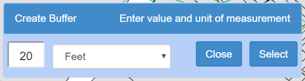
Select by creating a buffer. This option allows you to create a buffer around a selected object (point, line, or polygon). That buffer can then be used to select other objects. For example, you can select a line (a street, a pipe section, or a transmission line) and create a 50 foot buffer around that line.
To do this, follow these steps:
- First, select (click on) the desired map feature(s) that will be the source of the buffer.
- Then click the buffer icon from the menu of selection tools.
- The Create Buffer dialog appears, and a default buffer is drawn around the selected map feature.
- Change the buffer distance value or corresponding unit of measurement to modify the buffer.
- Choose a layer from the Select a Layer menu to make one layer selectable.
- Click the Select button, and the buffer will be used to select all the selectable features within the buffer.
This buffer method can also be executed from the Linear Work Orders tools. Look for the buffer button there.
Toggle within/overlaps. This feature controls how features are selected when using a polygon selection method. When the button icon arrows are pointing towards each other, within is on. This means that only objects that are 100% inside the selection polygon will be selected. For example, when selecting parcels, if almost all of a parcel is inside the selection polygon, but one corner is outside, that parcel will not be selected. When arrows are pointing away from each other, overlaps is on, and that parcel will be selected, as well as all other parcels partially inside the polygon.
Note: The user can select as many features as desired at once, but selecting more than 1000 features may require a significant time to process.
Manipulating map selections
Once you have items selected on the map, the following options are enabled:
Toggle Multi-select. When multi-select is enabled, new selections will be added to the existing list. When disabled, new selections will replace the previous list. When multi-select is enabled, the button will be darkened. when disabled, it will be lighter. Try it here by clicking the button to see the color change.
Zoom to the current selections. Click this button to zoom the map extent to center on all of the items in the Map Selected Features window.
Add current selections to Maximo list. This takes map selections and puts them in the List tab of Maximo. If the selection type doesn't match that of the currently open app in Maximo, they will not be added to the list, but in some cases, will filter the List tab results.
For example, if the selections are assets, but the Work Order Tracking app is open, clicking the button will bring up a list of work orders for the selected assets. If the map selections are work orders, and Work Order Tracking is the current app open in Maximo, and you click the plus icon, then those map-selected work orders will be displayed on the List tab in Maximo.
Subselect from current selections. Basically, a cropping tool to narrow selections if undesired features were selected. Drag your mouse to lasso current selections you want to keep.
Open the action menu. The action menu has various functions that can be performed on the currently selected features. These actions differ depending on the type of feature (e.g. work orders vs. assets). Actions allow you to create or update multiple records at once. Simply select a specific type of assets, locations, or work orders on the map. Then apply an action to update the selected items. All of the selected features must be of the same type for the action menu to be enabled. Any actions performed in the action menu will be applied to all selected features.
Common work order actions:
- Set WO Lead
- Set WO Status
- Set WO Group
- Set Target Date
- ...and more.
- Create a batch of work orders, based on the current work order
- Create a batch of work orders, based on a job plan
- Set asset/location status
- ...and more.
Talk with your Maximo administrator to get details on actions enabled for your environment.
Select by a pre-defined polygon.This option appears when exactly one polygon object is selected. This will use the selected polygon to select other objects within the polygon. It can be used when the user would like to select all of the features inside of a specific polygon area. For example, all valves can be selected within a specific parcel.
Set related work order on current service request. This option appears only in when the user is in the SR app in Maximo, when exactly one work order is selected. Clicking the button will then append the selected work order to the current service request as a related record. Note: Be sure to save the service request to save your changes.
Remove selection. The small red trash icon on each selection removes that individual selection from the list.
Set asset or location. The hammer on each selection (except work orders) sets that selection as the asset or location on the work order open in Maximo. If no work order is open in Maximo, this icon will do nothing. Note: This icon will only appear when the work order tracking app is open.
Item tooltips: double-click on the description of any item in the list to get a tooltip containing more information (from Maximo data and/or GIS data) about the feature. Tooltips are configurable, so if there is a field that you would like to see in the tooltip, contact an administrator.

The tooltip window can contain wealth of additional configurable information and options. This includes:
- Open a meter entry form, for entering meter readings or inspection information.
- Open a work order creation or edit form.
- Launch a detailed report of asset history, including meter readings and work orders.
- A live view of all the associated GIS attribution.
- A live view of all asset detail and specifications.
- ...and more.
Creating and Editing Work Orders from the Map
After you've selected an asset or location from the map, you can create a new work order for that feature. In the visible tooltip, click on "Create Work Order" to open the work order form. From there, enter in the information and submit. The new work order will be created in Maximo and displayed on the map.
You can edit existing work orders the same way, by simply clicking on the work order icon and choosing the "Edit Work Order" option to display the work order form. From there you can update status, assign work, and more.

Saved Vicinities
The Saved Vicinities drop-down menu is a very simple way to create and use map bookmarks.
Home Vicinity
A home vicinity is included by default, which can be edited with the first save button:
Clicking the save button will set the current map extent as the home vicinity (i.e. the default vicinity on startup).

Custom Vicinities
At the bottom of the drop-down menu is a text box where custom vicinities can be named and saved. It will then appear in the drop-down menu as a saved vicinity which can be navigated to by clicking on it, or deleted with thebutton to the right of the name.
These extents are saved on a per-user basis. Users cannot see or use each others saved vicinities. Two vicinities cannot be created with the same name by the same user.
Legend Window
The Legend window displays all of the layers that exist in the map. There are two main types of layers: work order layers and GIS/Location/Asset layers. The first two groups in the legend contain work order layers.
Work Order Layers
The first group, Work Order Layers, contains the work order layers set up by the
system administrator. Everyone can see these layers. The second group contains user-defined
work order layers, set up by the user and people in their Maximo person and security groups.
To see how to do this, see the Custom Work Order Layers section of this guide.
Work order layers cluster together, meaning that when there is more than one work order in
the same area, only one icon will show. To better see what is happening here, the user can
click the
button to turn a number label on and off for the layer. The user can also click the check box next
to any work order layer to turn it on or off in the map.
GIS/Location/Asset Layers
These layers are defined by the system administrator, and are contained in all of the legend groups after the work order layers groups. Sometimes, some of the layers in this section of the legend will be grayed out. As the user zooms in and out, some layers will not be visible at certain zoom scales. The layers that are not visible on the map will be grayed out in the legend, but retain the same functionality.
Legend Setup
The user can customize what layers are shown in their map and legend by clicking the button on the header of the legend window. All of the GIS/Location/Asset layers will expand and check boxes will appear on the right side of all of the layers. Check all the layers and layers groups that should be included, and uncheck those that should be left out. Then, click the Save Legend Settings button or the button to save the setup.
Note: MapEngine saves these settings, so however the user leaves the legend window when closing it or MapEngine is how it will appear the next time it is opened.
Custom Work Order Layers
Custom work order layers are just that: Layers that you as a user can define yourself. All custom work order layers are defined by a where clause defined on the Maximo List tab. This where clause can be used to define which work orders to include in the layer. Every work order layer also has a symbol to differentiate it on the map.
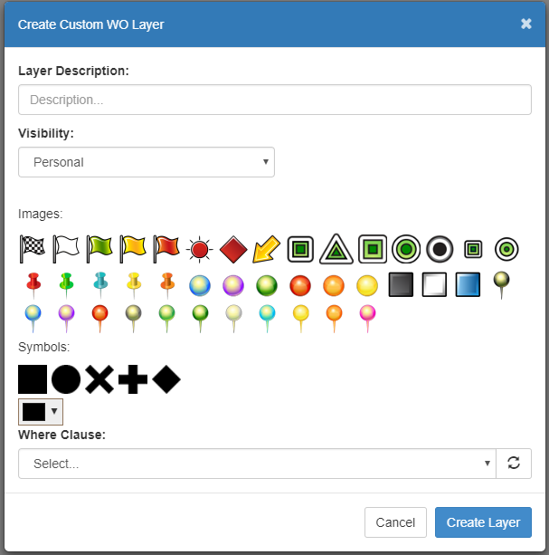
To create a work order layer start by clicking the Create Work Order Layer button in the User-Defined Work Order Layers group of the Legend Window. Then this window will show up:
Give the layer a name in the Description field, choose a visibility (Personal, group, or crew), and choose a symbol. Images will appear as they are; symbols can change color using the color picker at the bottom of the dialog. Then a where clause needs to be chosen. The where clause selector will include all Maximo saved queries for Work Order Tracking. The user can choose one of these, or use the current query in Maximo as the where clause. In order to do this, the user will need to open the where clause window in Maximo.
In the Maximo list tab, click on the down arrow next to Advanced Search. Then click on where clause.
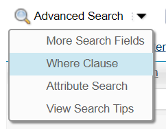
The where clause being used for the current query should appear. Then, select the "Use Maximo where clause" option in MapEngine, and click "Create Layer". The layer will then be saved.
Editing existing custom work order layers. The user can also change the name and icon of any custom layer at any time, by clicking the Edit icon next to the layer name. In the Edit dialog, simply change the description or select a new icon or symbol, then click save.
If you have the proper administrative access, you can promote the custom layer to be a public layer that is visible to all users. To do this, simply click the Make Layer Public checkbox.
Summary Mode
Summary Mode is a powerful filtering tool that allows the user to see how many work orders have certain attributes and also allows the creation of custom work order layers based on those attributes.
Summary Mode is found on the header of the legend window.
To start, click the button to enter Summary Mode. Then choose a work order layer from the drop-down menu to summarize. The user may also choose to summarize all work orders in a drawn rectangle or in the current extent.
Once a layer is chosen, then select a field to summarize. For example, if status is chosen, something like this may appear, summarizing work orders by status:
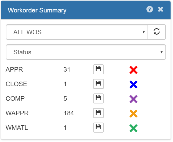
Each status is shown, along with the number of work orders with that status in the layer chosen, and a save button with an icon. These categories (in this example, statuses) will also be drawn on the map as temporary work order layers.
Note:The normal work order layers will not be available during summary mode.
Click the save button to save it as a user-defined work order layer. It will be saved with the displayed icon,
and will be assigned a name describing its category. The name and icon can be changed in the legend window (see Custom Work Order Layers
section).
When finished with summary mode, click the exit button at the bottom right. Any unsaved temporary layers will be deleted, and the normal layers will return, along with any saved during summary mode.
Search
The search window allows the user to search for different types of information,
depending on what searches the system administrator has set up.
To perform a search, open the search window, click on the drop-down menu, and select a search category:
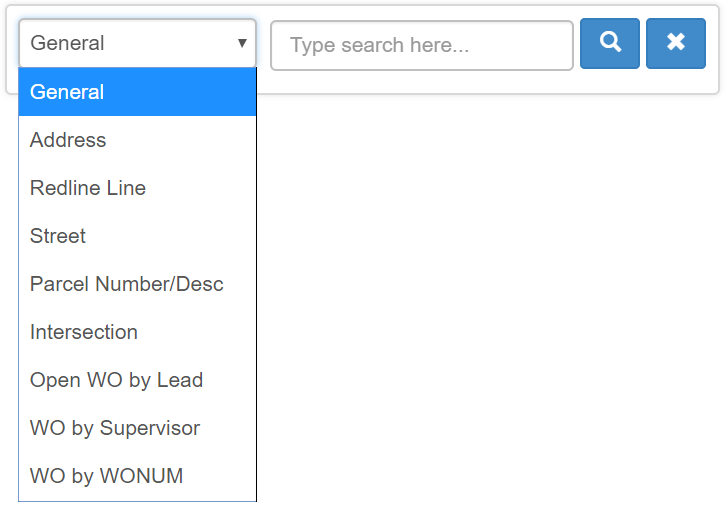
Then type the search parameters in the search box. The available searches will depend
on what the system administrator has set up.
Go To Menu
The Go To menu provides several integration options so you can "go to" certain Maximo or GIS records. It can be used to pull information from Maximo into the map, or to send asset management information from the map into Maximo.
The Go To Location / Go To WO Location button will get the location on the object open in the Maximo window and zoom to it on the map. Similarly, the Go To Asset / Go To WO Asset button will get the asset on the object open in the Maximo window and zoom to it on the map.
The Go To WO/SR from Maximo button will zoom to the currently open work order/service request in the Maximo window.
The Map Maximo List Items button will pull all items out of the current list in Maximo and select and zoom to them on the map.
The Open Google Maps button will open a Google Maps tab, zoomed to the current center of the MapEngine map.
Building Mode
If the system administrator has created map layers that have children layers (such as buildings and rooms), when you select them, you can go into building mode. Building mode allows you to see the children layers on different floors or levels of a layer. When you select one of these objects, you will be asked if you want to enter building mode. Click OK to enter Building Mode. You can then change floors in the drop-down menu on the bright red box on the bottom left. Click exit to leave Building Mode.

Work order behavior in buildings. When you view work orders assigned to a building, all the work orders are displayed on top of that building. When you enter building mode, you'll only see the work orders for the respective floor you designate.
Measurement Tool
Clicking on this icon opens the Measurement Tool. Once the tool is open, start clicking on the map, and dragging. You will begin to see a red line being drawn. Click again on the map to create a new intersection in your measurement. Double-clicking ends the measurement and displays the measurement value. You can use the drop-down menu to change the units of the measurement.
My Location
Clicking on this icon zooms the map to the users current location, which will be denoted by a blinking blue dot. Note: This feature requires Maximo to be running in SSL mode, with a valid security certificate.
Proposing GIS Changes
Sometimes the map, GIS attributes, and Maximo specifications don't match what a user sees in the real world. For instance, an asset on the map may be positioned incorrectly or its observed attribute might be different than what the map or Maximo states. Also, users in the field may find assets that don't appear on the map.
So, a MapEngine user can mark on the map the real position of an asset, update or provide new GIS feature values, and send all this information to the GIS administrator via an automated Maximo work order, by following the instructions below:
To propose changes to existing GIS features
- Click on the asset in question, on the map.
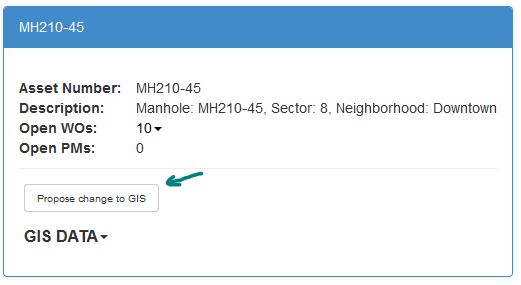
- Double-click on the description of the selected asset in the Map Selected Features list to reveal the Asset Info Window.
- Click on the button: Propose GIS Changes.
- For position discrepancies, click on the map and slide it, positioning the indicator pin to the approximate observed location of the asset. Note: The pin indicates where the work order will be placed, so the GIS admin can understand where the item should be positioned.
- In the form that appears, in the Notes field, make notes describing any discrepancies you want the GIS admin to review.
- If any other attribution needs to be changed, enter the new values in the available fields. These suggestions will be sent to the GIS admin for review.
- Click Select this Location to submit the request.
- A work order will be created in Maximo and a work order symbol will be placed on the map. Depending on your installation, a notification will be sent to the proper person for review.
To report the finding of previously unmapped assets
- Click on the Go To menu and choose Found new GIS feature
- Position the indicator pin to the approximate observed location of the newly-found asset. Note: The pin indicates where the work order will be placed, so the GIS admin can understand where the item should be positioned.
- Click Select this Location.
- In the dialog that appears, click the drop-down menu and select the type of asset discovered, and then click OK.
- In the form that appears, enter in any attribute information observed, and in the Notes field make notes describing anything you want the GIS admin to review.
- Click OK to finish and submit the work order.
- A work order will be created in Maximo and a work order symbol will be placed on the map. Depending on your installation, a notification will be sent to the proper person for review.

Linear Work Orders
For work orders on linear assets, MapEngine provides the option to visualize these work orders as lines, instead of points. These "linear" work orders are visualized by placing a line along the asset, representing the start and end of the work order.
The work order start and end measures are defined in the work order, using the start and end measure fields found under the Linear Segment Details section. Typically, these fields are the MULTIASSETLOCCI.STARTMEASURE and MULTIASSETLOCCI.ENDMEASURE fields in Maximo.
NOTE: This section is not typically visible until a linear asset (with a linear measurement) is added to the work order.

The following is the process to create and edit a linear work order, using MapEngine:
Create a new linear work order
- Start a new work order in Maximo.
- Click on a single linear asset in MapEngine to select it. (Only works one at a time.)
- In the Map Selected Features list, click the hammer icon corresponding to the linear asset to set the Maximo asset field.
- Click on the button: Edit WO Linear measurements.
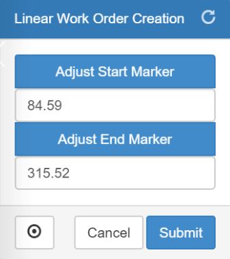
- The Linear Work Order Creation window will appear, with the start and end measurements defaulting to the full length of the asset. On the map, the start and end markers will be placed at each end of the linear asset.
- To set the start measure, click on the Adjust Start Marker button in the dialog. Then move your cursor to the point on the linear asset where you want the start to be, and click.
- To set the end measure, click on the Adjust End Marker button in the dialog. Then move your cursor to the point on the linear asset where you want the end to be, and click.
- To update/set the Maximo linear work order start and end measurements, click the Submit button.
- Note the updated fields in Maximo and save the work order.
- A work order will be created in Maximo and a linear work order symbol (a line) will be placed on the map, based on the start and end measures.
Editing existing linear work orders
- Open an existing linear work order in Maximo.
- Click the Go to Current WO option from the Go To menu.
- Click on the button: Edit WO Linear measurements.
- The Linear Work Order Creation window will appear, and start and end markers will be placed on the linear asset.
- Repeat the steps from the previous section to update the linear measurements.